Ados

GTR 210

Gas Transmitter
GTR 210

Application

The gas transmitter ADOS GTR 210 is suitable for continuous measurement of gases in normal areas and areas where there are risks of explosion.

Available basic versions:
– Ex-version: with current interface 4-20 mA
– Standard: 4-20 mA or LON®-4-wire techniques
– Comfort: 4-20 mA, with additional changeover
   contacts for alarms and failure

By employing 6 different types of sensor, noxious, explosive and non-combustible gases and vapours can be measured.

Display of the measured gas concentration and the adjustable alarm thresholds, are shown on a multi-colour graphic display. The keyboard input is by way of a touchpad.

A current signal is generated that is proportional to the measured concentration of gas, which is transmitted to an evaluation unit placed in a safe area, away from any dangers of explosion.

The type test of the explosion-protected gas transmitter, is completed by the DEKRA.

ATEX certificate: DEKRA 11ATEX0257 X
IECEx certificate: IECEx DEK 11.0090 X
Type of protection: Ex d e ia mb IIC T4 Gb
SIL 1 & functional test:
ATEX Certificate –> BVS 12 ATEX G 001 X

Fields of Application

  • Chemical industry
  • Manufacture of paints and varnishes
  • Plastics processing plants
  • Sewage works
  • Gas-fired boiler systems
  • Liquid gas storage houses
  • Laboratories
  • Oxygen concentration measurements
  • Refineries
  • Cold storage houses (Ammonia monitoring)
  • Paint spraying booths
  • ... and many more.

NEW!
Advanced field of application: marine (option MED)

The gas transmitter product family GTR 210 with the option MED fulfills the requirements of the Marine Equipment Directive 96/98/EC and its annual updated addendum 2013/52EU. The conformity with the above mentioned regulation has been certified by the ship safety division of the German Government Safety Organisation for Transport and Transport Economies. The compliance with international IEC standards and the durability against saltwater was verified. The gastransmitter GTR 210 can now be installed under deck as well as on deck (weather zone) under harsh conditions.

The field of application extends to:

  • gas tankers
  • container ships
  • offshore platforms
  • applications in aggressive environments

The IR sensor

The test gas flows through a measurement chamber that incorporates an IR radiating source and a two-channel
infrared detector. The intensity of the infrared radiation is reduced as it passes through the gas molecules.The concentration of the gas can then be calculated by the magnitude of the reduction in intensity.

Since only absorption of the wavelength specific to the gas under test in relation to the wavelength not absorbed by a test gas is considered, interference due to dust, ageing etc., is almost compensated.


1 = Infrared-radiating source
2 = Test gas
3 = Diffusion filter
4 = Infrared-detector
5 = Measurement chamber

TGS sensor

The TGS sensor contains a semiconductor sensor, which is ­constructed on SnO2-sintered N-substrate.

When combustible or reducing gases are absorbed by the surface of the sensor, the concentration of the test gas is determined by the change in conductivity.


1 = Circuit voltage
2 = Heating voltage
3 = Load resistor

TOX sensor

The TOX sensor is a measurement system with electro-chemical cell, where the sampled gas is measured by diffusion. In the case of oxygen measurement the oxygen content is in an electrolyte, thus producing a small flow of current (electro-chemical process).
At a constant air pressure, this current is directly proportional to the oxygen concentration in the sampled air.

1 = Anode
2 = Electrolyte
3 = Cathode
4 = Diffusion path
5 = Diffusion filter
6 = Test gas

GOW sensor

The GOW sensor functions on the principle of thermal conductivity. Two rhenium-tungsten resistors are used as a measuring element, where the comparison element is subjected to normal ambient air and the measuring element is subjected to the test gas. Any change in the concentration of gas at the measurement element, causes a change in temperature, which is due to the variation of conductivity.
The resultant change in resistance is a direct measure of the gas concentration.

1 = Diffusion filter
2 = Test resistor
3 = Comparison resistor

The PID sensor

The sampled gas flows through a measurement chamber, that incorporates a UV radiating source and a pair of
electrodes with opposing polarity. The gas molecules to be detected are ionized by the UV radiation.
The resulting positively charged molecules and the electrons are attracted to the relevant electrode. The current generated is a measure of the gas concentration.

Using the PID measuring head, volatile organic compounds (VOC) can be measured, the ionisation potential of which is less than the energy in the UV radiating source (10,6 eV), e.g. aromatic hydrocarbons like toluol (C7H8) and xylene (C8H10) as well as chlorinated hydrocarbons like trichloroethylene (CHCl3). The detection of toxic gases like phosphine (PH3) is also possible.


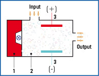
1 = UV radiating source
2 = Test gas
3 = Capacitive charge
      measurement

VQ sensor

The head of the VQ sensor functions on the principle of heat ­reaction. When combustible or reducing gases or ­vapours come in contact with the measuring element, they are subjected to catalytic ­combustion, which ­causes a rise in temperature; this rise causes a change in the resistance of the measuring element which is used as a measure of the component of gas being tested.
The inert element is for compensating the temperature and conduc­tivity of the test gas.

1 = Catalyzer pellistor
2 = Electric connections
3 = Inert pellistor
4 = Diffusion filter

Technical data - for standard sensor elements

special versions on request
Type TGS VQ GOW
Measurement method Semiconductor Heat reduction Thermal conductivity
Measurement range ppm ranges
to 100 % LEL
ppm ranges
to 100 % LEL
from 0-5 Vol%
to 0–100 Vol %
Percentage error
of f.s.d.
±5 % ±5 % ±5 %
Response time (t90) approx. 60 s approx. 60 s approx. 40 s
Pressure effect 1 % 1 % 1 %
Mounting position optional ± 90° from the vertical mounting position optional ± 90° from the vertical mounting position optional ± 90° from the vertical mounting position
Application Poisonous,
combustible and
explosive gases
in the LEL region
Poisonous,
combustible and
explosive gases
in the LEL region
Gases exhibiting
substantial differences
in thermal conductivity,
compared to air
Versions available industrial (Al),
industrial (VA)-
and Ex-version
industrial (Al),
industrial (VA)-
and Ex-version
industrial (Al),
industrial (VA)-
and Ex-version
Expected lifetime
of the sensor
approx. 5 years, when used
for gases not causing
catalytic poisoning
approx. 4 years, when used
for gases not causing
catalytic poisoning
approx. 5 years, when used with gases that do not attack aluminium, rhenium-tungsten or gold
Warranty 2 years 2 years 2 years
Dimensions
(W x H x D)
150 x 175 x 105 mm 150 x 175 x 105 mm 150 x 175 x 105 mm


Type TOX IR PID
Measurement method Electro-chemical reaction Infrared Photo-Ionisation
Measurement range ppm ranges
to 0–100 Vol %
0-100 % LEL CH4, C3H8,
C2H2, 0-100 Vol % CH4
0 –1, 2, 3, 4, 5 Vol % CO2
0 – 200 ppm to
0 – 2.000 ppm
Percentage error of f.s.d. ±3 % ±3 % ±5 %
Response time (t90) approx. 60 s approx. 60 s CH4
approx. 60 s CO2
approx. 120 s
Pressure effect 1 % 4 % 1 %
Mounting position optional ± 90° from the vertical mounting position optional ± 90° from the vertical mounting position optional ± 90° from the vertical mounting position
Application O2, CO, NH3, NO2, SO2, H2S and others CH4 (Vol %; LEL) Propane (LEL), CO2 (Vol %) e.g. C7H8, C8H10
CHCl3, PH3
Versions available industrial (Al),
industrial (VA)-
and Ex-version
industrial (Al),
industrial (VA)-
and Ex-version
industrial (Al),
industrial (VA)-
and Ex-version
Expected lifetime
of the sensor
12 months to 7 years
depending on the
measuring cell
approx. 5 years  12 months
Warranty 12 months 2 years  6 months
Dimensions (WxHxD) 150 x 175 x 105 mm
150 x 175 x 105 mm 150 x 175 x 105 mm


Type TOX O2
Measurement method Electro-chemical reaction
Measurement range ppm ranges
to 0–25 Vol %
Percentage error of f.s.d. ±2 %
Response time (t90) approx. 30 s
Pressure effect 1 %
Mounting position optional ± 90° from the vertical mounting position
Application O2
Versions available industrial (Al),
industrial (VA)-
and Ex-version
Expected lifetime
of the sensor
approx. 5 years
Warranty 12 months
Dimensions (WxHxD) 150 x 175 x 105 mm

Technical data - for all 3 basic versions of gas

Type GTR 210 Ex-version GTR 210 Standard GTR 210 Comfort
Supply voltage 24 V DC +10% / -25% 24 V DC +10% / -25% 230 V AC, 50 Hz
115 V AC, 60 Hz (optional)
Power consumption 4 W 4 W 10 VA
Interface 3-wire techniques with current interface 4 – 20 mA 3-wire techniques with current interface 4 – 20 mA or LON®-4-wire techniques 1 current output 4 – 20 mA
4 potential-free changeover contact for alarm/failure
1 digital input for cancelling alarms
equipment group / category II 2G, II 2D
Ignition protection Ex d e ia mb IIC T4 Gb
Ex tb IIIC 135° Db 
none Ex none Ex
Type of protection ATEX certificate:
DEKRA 11 ATEX 0257 X
IECEx certificate:
IECEx DEK 11.0090 X
EN60079-29-1:2016 EN50104:2019
EN50271:2018
   
SIL 1 & functional test ATEX certificate:
BVS 12 ATEX G 001 X


Option MED / Marine Equipment Directive Directive 2014/90/EU
Approval 213.053


Temperature range - possible limitations due to the used sensor element -25 °C to +60 °C -25 °C to +60 °C -25 °C to +60 °C
Protection class IP 66 / IP 67 IP 54 or IP 66 / IP 67 IP 54 or IP 66 / IP 67
Weight 2,3 kg 1,8 kg 2,0 kg